


Ct for Single-phase Electricity Meters
The power-frequency withstand voltage between primary winding to secondary winding and to the ground shall be 3kV (r.m.s). When Class II protective insulation is specified, it shall be 4kV (r.m.s). By using dielectric strength tester to perform the test under rated 3kV/4kV voltage, leakage current 1mA for 1 minute, no breakdown from current transformer is allowed.

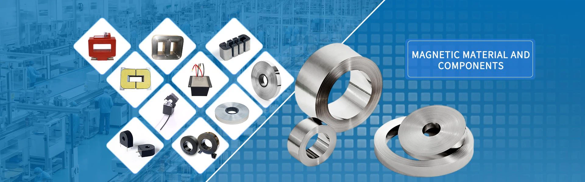
Product Introduction
Micro Current Transformers
KEY PERFORMANCE INDEX:
Rated Insulation Level
Power-Frequency Withstand Voltage
The power-frequency withstand voltage between primary winding to secondary winding and to the ground shall be 3kV (r.m.s). When Class II protective insulation is specified, it shall be 4kV (r.m.s). By using dielectric strength tester to perform the test under rated 3kV/4kV voltage, leakage current 1mA for 1 minute, no breakdown from current transformer is allowed.
Insulation Resistance
The insulation resistance of the primary winding to the secondary winding and to the ground should be larger than 500MΩ.
Polarity
The polarity of current transformer is subtractive. When primary is energized from terminal L1 to terminal L2, the induced secondary current flow is from terminal K1 via burden circuit to terminal K2.

Errors
Current Error (Ratio Error)
The error which a transformer introduces into the measurement of a current and which arises from the fact that the actual transformation ratio is not equal to the rated transformation ratio.
Phase Displacement
The difference in phase between the primary and secondary current vectors, the direction of the
phasors being so chosen that the angle is zero for an ideal transformer.
The phase displacement is said to be positive when the secondary current phasor leads the primary current phasors. It is usually expressed in minutes(’) or centiradians(Crad.)
Rated Transformation Ratio
Ratio of the rated primary voltage or current to the rated secondary voltage or current.
Accuracy Class
A designation assigned to an instrument transformer, the ratio error and phase displacement of which remain within specified limits under prescribed conditions of use.
Error Limits
CT (Current Transformer) Error Limits
|
Accuracy Class |
Ratio Error(±%) with the percentage(%) of input current |
Phase Error with percentage(%) of input current |
|||||||
|
0.01In |
≥0.05 In |
0.01In |
0.05In |
0.2In |
In |
2In |
3In |
Imax |
|
|
0.5 |
1.0 |
0.5 |
90 |
45 |
30 |
30 |
30 |
30 |
30 |
|
0.2 |
0.4 |
0.2 |
30 |
15 |
10 |
10 |
10 |
10 |
10 |
|
0.1 |
0.2 |
0.1 |
15 |
8 |
5 |
5 |
5 |
5 |
5 |
|
0.05 |
0.1 |
0.05 |
8 |
4 |
2 |
2 |
2 |
2 |
2 |
Note:
1) Between the current 0.2In and Imax, we take the mean value of the maximum phase displacement ![]() and the minimum phase displacement
and the minimum phase displacement ![]() as
as ![]() , take the difference between the phase displacement of current i
, take the difference between the phase displacement of current i ![]() and the mean value
and the mean value ![]() as the phase error of current i :
as the phase error of current i :![]()
2) The actual error curve of the current transformer should not exceed the range of the line formed by the error limit line of Table 1.
3) 0.02 class and above , current transformer is according to the definition of JJG 314-2010.
PT (Potential Transformer) Error Limit
|
Accuracy Class |
Ratio Error(±%) with the percentage (%) of input voltage |
Phase Error with percentage(%) of input voltage |
||||
|
0.8Un |
1.0Un |
1.2Un |
0.8Un |
1.0Un |
1.2Un |
|
|
0.5 |
0.5 |
0.5 |
0.5 |
20 |
20 |
20 |
|
0.2 |
0.2 |
0.2 |
0.2 |
10 |
10 |
10 |
|
0.1 |
0.1 |
0.1 |
0.1 |
5 |
5 |
5 |
|
0.05 |
0.05 |
0.05 |
0.05 |
2 |
2 |
2 |
|
Note: 1) Phase error is equal to phase displacement minus the rated phase displacement. 2) The rated phase displacement is defined as the average value of the phase displacement between the value 0.8Un, 1.0Un and 1.2Un 3) The actual error curve of the voltage transformer should not exceed the range of the line formed by the error limit line of Table 2. 4) For a rated voltage factor 1.9, voltage transformer in the 1.9Un voltage with continuous operation with the 4H that should be intact. This error is not specified. 5) 0.02 class and above , voltage transformer is according to the definition of JJG 314-2010. |
||||||
FAQ:
Q: Are you trading company or manufacturer?
A: We are professional manufacturer specialized in the design、development and production of new-type amorphous、nanocrystalline、silicon steel sheets and other magnetic materials and components.
Q: What’s your production capacity ?
A: The annual production capacity of amorphous&nanocrystalline ribbon is 600 tons;
The annual production capacity of power electronic core is 35 million;
C-type iron core annual production capacity of 240 tons;
The annual production capacity of reactors is 50,000;
The annual production capacity of precision transformers is 40 million;
Three steps to start your customization today!
1. Tell us what you need,please call 021-63306968 Or send email to :sales@sunbowgroup.com
As every application has its own characteristics and requirements.
We provide customized services according to your application
Just tell us your design concept and basic parameters
2. Get solution & quote
We will work on the best solution and provide primarily specification& quote for your review.
3. Sample production and mass production
We will start mass production after customer confirmation and validation of samples.
our workshop

our equipment


our testing


our certification

our production process

our exhibition

Hot Tags: ct for single-phase electricity meters, China ct for single-phase electricity meters manufacturers, suppliers, factory, Current Transformer for Current Monitoring, closed loop current sensor, Energy Meter Parts, toroid current transformer, Current Transformer, Ct for DC IMMUNE Electricity Meters


Send Inquiry