Current Transformer

Your Professional Current Transformer Manufacturer in China

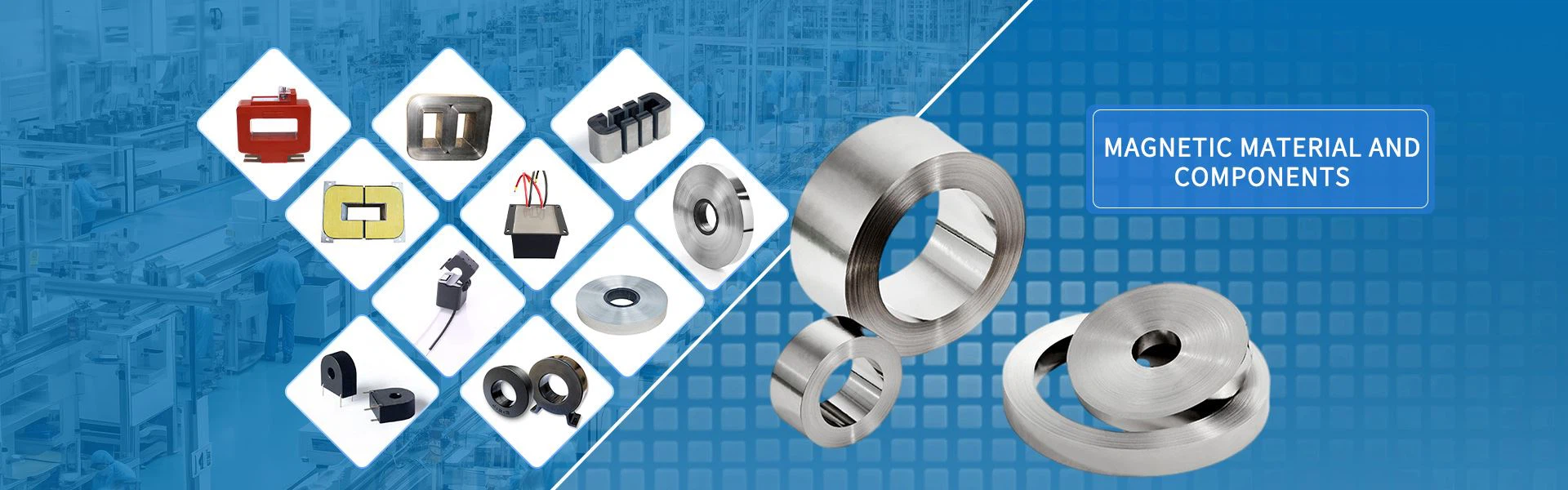
Sunbow Group specializes in the design, development and production of new-type amorphous, nanocrystalline, silicon steel sheets and other magnetic materials and related products. The company's main products include various types of amorphous, nanocrystalline ribbons and high and low voltage current transformer cores, precision current transformer cores, common mode inductor cores, PFC inductor cores, high frequency power transformer cores and related devices.

Customized Solutions

We are at the forefront of a design led approach to delivering challenging and custom solutions for magnetic cores or components for production. Whether your need is simple or complex, we can develop a solution to achieve your goals. With in- house experts we can design, develop and test prototypes that meet performance and environmental requirements of your application.

Advanced Equipment

The company has advanced equipment such as large-scale vacuum smelting furnaces, pressure spraying belts, various magnetic annealing furnaces and close cooperation with domestic scientific research institutions and universities, which ensures the company's R & D ability and product quality.


Complete Qualifications

At present, the company has two production bases, with a number of patented technologies, and has passed ISO9001, IATF16949 quality management system certification. All products have passed ROHS, SGS and other environmental protection certifications.


Wide Range of Applications

The company mainly serves the fields of new energy vehicles, photovoltaic power generation, wind power generation, smart home appliances, smart meters, wireless charging, and various power supplies, inverters, filter inductors, and shielding materials in the national strategic emerging industries.


Introduction of Current Transformer
 

A current transformer (CT) is a type of transformer that is used to reduce or multiply an alternating current (AC). It produces a current in its secondary which is proportional to the current in its primary. Current transformers, along with voltage or potential transformers, are instrument transformers. Instrument transformers scale the large values of voltage or current to small, standardized values that are easy to handle for measuring instruments and protective relays. The instrument transformers isolate measurement or protection circuits from the high voltage of the primary system. A current transformer provides a secondary current that is accurately proportional to the current flowing in its primary. The current transformer presents a negligible load to the primary circuit. Current transformers are the current-sensing units of the power system and are used at generating stations, electrical substations, and in industrial and commercial electric power distribution.


Advantages of Current Transformers

Safety Isolation
CTs provide electrical isolation between the primary circuit (high current side) and the secondary circuit (low current side). This isolation enhances safety by preventing high currents from reaching measuring and monitoring equipment.


Wide Range of Applications Versatility
Current transformers are suitable for a wide range of applications, from protecting electrical equipment to monitoring power consumption in industrial processes and renewable energy systems.

Accuracy High Precision

Current transformers are known for their exceptional accuracy in measuring current. They provide reliable and precise readings even under varying load conditions.

Reliability & Durability

CTs are robust and designed for long-term use. They can withstand harsh environmental conditions and continue to provide accurate measurements.

Easy Installation Simplicity

Current transformers are relatively easy to install and maintain, making them accessible to a broad range of users.


Current Transformer for Electricity Meter


Construction of Current Transformers

The core of the current transformer is built up with lamination of silicon steel. For getting a high degree of accuracy the Permalloy or Mumetal is used for the making cores. The primary windings of the current transformers carry the current which is to be measured, and it is connected to the main circuit. The secondary windings of the transformer carry the current proportional to the current to be measured, and it is connected to the current windings of the meters or the instruments.
The primary and the secondary windings are insulated from the cores and each other. The primary winding is a single turn winding (also called a bar primary) and carries the full load current. The secondary winding of the transformers has a large number of turns.
The ratio of the primary current and the secondary current is known as a current transformer ratio of the circuit. The current ratio of the transformer is usually high. The secondary current ratings are of the order of 5A, 1A and 0.1A. The current primary ratings vary from 10A to 3000A or more.
The working principle of the current transformer is slightly different from the power transformer. In a current transformer, the load’s impedance or burden on the secondary has slightly differed from the power transformers. Thus, the current transformer operates on secondary circuit conditions.


Key Parameters of Current Transformers
 

When selecting a current transformer for a specific application, there are several crucial parameters to consider:

Accuracy Class

This indicates the degree of error within the transformer’s output. Different applications require different levels of accuracy.

Rated Primary Current

This refers to the nominal value of the current that the transformer is designed to measure.

Burden Rating

The burden of a current transformer describes the total impedance of the secondary circuit in VA (Volt-Ampere) that the CT could supply at the rated current and accuracy.


Three Types of Current Transformers
 

Window Current Transformers
A window current transformer is a transformer that consists of a secondary winding wrapped around a core and the primary sent through the opening in the core. After the secondary is wound around the core, the assembly is placed into a mold, and an insulating material is injected around the transformer. Taps are brought out from the winding. A power line is passed through the window and acts as the primary. This completed assembly is referred to as a window current transformer.


Bar Current Transformers
A bar current transformer is a special type of window current transformer with a solid bar placed permanently through the window. A bar current transformer can withstand the stresses of heavy overcurrent. To avoid magnetic stresses that could destroy the bus and damage the transformer, care must be taken to properly mount these transformers with respect to adjacent conductors. This type of transformer is typically found on installations where the potential is 25kV or less.


Wound Current Transformers
A wound current transformer is a transformer with separate primary and secondary windings wrapped around a laminated core. A wound current transformer is designed so that the primary winding consists of one or more turns of large cross-section wire connected in series with the circuit to be measured. This kind of current transformer is located on the high-voltage side of substations and contains a primary conductor that carries the current and a wound current transformer for the output current.


The Functions of Current Transformers

The main function of the current transformer is to convert the large current in the AC circuit into a certain proportion of the small current (the Chinese standard is 5 amperes) for measurement and relay protection.
In the process of power generation, transformation, transmission and distribution, due to different electrical equipment, the current is usually from tens of amps to tens of thousands of safe, and these circuits may also be accompanied by high voltage. Therefore, in order to monitor and measure the circuits of these lines, while addressing the dangers posed by high voltages and high currents, current transformers are required at this time. Electrician's clamp meter, which is a device used to measure alternating current, its clamp is a through-core current transformer.

Ct for Single-phase Electricity Meters


What is Current Transformer and Potential Transformer
 

Current Transformer

Also known as CTs, current transformers are devices that measure alternating current. They are widely used to measure high magnitude currents.
A current transformer essentially lowers (steps down) a high current to a lower, safer level that you can manage properly. It steps down the current to be measured so that you can measure it with an average range ammeter.
Functions:
●Converting large primary currents into small 1A/5A current
●Providing the current for the coil of measuring device and protective relaying
●It separates primary voltage from secondary voltage.
Characteristics:
●The resistance of the instrument’s current coil with which the CT’s secondary winding is connected is small. The CT transformer operates under a state close to the short circuit under normal condition
●The primary winding is installed in series in the current.

Potential Transformers

On the other hand, potential transformers, also known as voltage transformers, measure an aspect of the power supply. While a current transformer measures current, the potential transformer measures voltage. The majority of American homes use different voltages for various purposes.
Functions:
●It measures and reduces high voltage values into lesser values
●Voltage transformers proportionally convert the high voltage into a standard secondary voltage of 100V or lower for easier utilization of protective and measuring instruments/devices
●To isolate the high voltage from electricians using the PT.

Difference Between Current Transformers and Potential Transformers

●Function: One of the major differences between CT and PT transformers is their functions. On the one hand, a current transformer reduces a high current to a safer and more manageable level that you can measure. It converts large primary currents into small 1A/5A currents that can be measured on the ammeter. On the other hand, a potential (voltage transformer) measures and reduces high voltage values into lesser values. It converts the high voltage into a standard secondary voltage of 100V or lower.
●Types: The current transformer is divided into two types, including wound and closed core. The potential transformer is also divided into two categories(types), including electromagnetic and capacitor voltage.


Applications of Current Transformers

Measurement
Current transformers help measure high voltage and high current circuits by translating them into manageable levels. This enables the safe monitoring and control of power flow, contributing to efficient grid operation.

Load Balancing
CTs can also be used in power factor correction systems. By accurately measuring the load current, they aid in balancing the load across phases, thereby improving system efficiency.

Protection
In power systems, protective relays ensure safety by disconnecting circuits when fault conditions occur. CTs provide the necessary input signals for these relays, allowing them to perform their job effectively.


What are the Different Materials Used in Current Transformers
 

There are various types of materials that are used in the current transformers. Following are some of them that are commonly found.

Amorphous Steel

This popular choice allows the creation of the perfect magnetic cores in the transformer. Thin metallic tapes are used together to reduce the eddy currents. This is a good and efficient option that is used in the current transformers nowadays.

Solid Iron Core

These cores are good if you want to increase the magnetic flux while retaining the magnetic field without increasing the iron. It is used in various transformers; however, they are not suggested for the ones used for AC appliances.

Nanocrystalline Transformer Core

The nanocrystalline transformer core is one of the most suitable materials that can be used for a current transformer. This core is made with one or more materials in nano value. They are excellent for the current transformers because of the fantastic benefits you can attain through this material.


Design and Manufacturing Process of the Current Transformer
Amorphous Reactor
Amorphous Reactor
Ct for Three-phase Electricity Meters
Common Mode Choke Coil

Design and Engineering
The first step is to have a detailed design and engineering plan. This includes determining the specifications, such as rated current, accuracy class, burden, insulation requirements, and physical dimensions. The design also includes the core material, turns ratio, winding configuration, and housing design.
Material Procurement
Once the design is finalized, the necessary materials are procured. This includes sourcing the core material, insulation materials, winding wire, bushings, terminals, and other components required for the CT.

Core Manufacturing
The core of the CT is typically made of high-quality silicon steel laminations. The laminations are cut and stacked to form the core shape specified in the design. The stacked core is then clamped and insulated to minimize core losses and improve the magnetic properties.

Winding
The primary and secondary windings are manufactured using insulated copper or aluminum wire. The winding wire is carefully wound around the core following the specified turns ratio and configuration. Insulation materials, such as insulation tape or varnish, are applied between the windings and layers to ensure proper insulation and prevent short circuits.

Assembly
The core with windings is then assembled with other components, such as bushings and terminals. The bushings provide electrical connections for the primary and secondary windings, and the terminals allow for external connections to the CT. The assembly is securely mounted within a housing or enclosure designed to provide mechanical protection and environmental sealing.

Insulation and Impregnation
The CT is subjected to insulation tests to ensure proper electrical insulation between windings and components. Insulation materials, such as epoxy resin or oil, may be used to impregnate the CT for enhanced insulation and to improve thermal performance.

Testing and Calibration
After manufacturing, the CT undergoes a series of tests to verify its performance and accuracy. This includes ratio tests, burden tests, accuracy tests, insulation tests, and other electrical tests specified by relevant standards. The CT may also be calibrated to ensure accurate measurement and protection capabilities.

Quality Control and Compliance
Throughout the manufacturing process, stringent quality control measures are implemented to ensure that the CT meets the specified design requirements and complies with relevant standards and regulations. This includes inspections, documentation, and adherence to quality management systems.

Packaging and Shipping
Once the CT passes all tests and quality checks, it is carefully packaged to protect it during transportation. Appropriate labeling and documentation are prepared, and the CT is shipped to the designated location.


Our Certificates


All products have passed ROHS, SGS and other environmental protection certifications.


productcate-749-300productcate-749-300


Our Testing Equipment


productcate-666-357productcate-665-357


Common Problem of Current Transformer


Q: What's a current transformer? And when to use it?

A: Measuring the intensity of the electric current is a good method to control the electrical consumption of equipment, in a building, an industrial site, a use, a warehouse. The presence of current consumption, the level of current-in amperes-are indicators of activity. The level of the current makes it possible, for example, to conclude on the level of operation of a machine (in standby, or the mode of operation-reduced, normal, intense). In a hotel, this makes it possible to deduce the presence of a person, or of an empty room whose electrical equipment is still active. In a building, this makes it possible to identify the level of (electrical) activity by zone. If the placement of a communicating electricity meter allows, on the one hand to measure the current, but also to recover the power and especially the energy consumed, there are many cases where the budget and / or the complexity of installation of an electric meter is not justified.

Q: How is a current transformer (ct) used in metering?

A: A current transformer (CT) is a type of instrument transformer used to measure the alternating current of an electric circuit. It consists of a primary coil which is the conductor carrying the current to the circuit being measured, and a secondary coil (or more than one) connects to a meter or other instrument. The current in the secondary coil is proportional to the current in the primary coil. A current transformer, like any other electrical transformer, has a main winding, with a single turn (the conductor), a core, and a secondary winding; The physical principles are the same as with a voltage transformer. A high Alternating Current, which is too strong for the meter, flows through the primary coil producing a magnetic field in the core, a low current in the secondary coil is then produced through the magnetic field in the core to safely measure the actual electrical current.

Q: What is the structure of current transformer?

A: Current transformers basically consist of three parts: a magnetic iron core, a primary winding wound on this core, and a secondary winding wound on this primary winding in the opposite direction. The current passing through the primary winding creates a magnetic flux on the magnetic iron core. This magnetic flux in the core causes a voltage to be induced on the secondary winding. The measuring device connected in parallel to the secondary winding creates a magnetic flux in the magnetic iron core in the opposite direction because the current passing through the secondary circuit is opposite to the winding direction. This magnetic flux balances the magnetic flux created by the current passing through the primary winding. For this reason, the secondary ends of the current transformers must be short-circuited by a measuring device or a load. Otherwise, a magnetic flux in the opposite direction will not occur and since the flux is not balanced, the magnetic iron core may heat up and fail. In addition, this situation poses a danger to users as it will increase the voltage at the secondary ends.

Q: What is a current transformer used for?

A: A current transformer is used to measure the high current passing through a line, and also as an insulation device between power circuits and metering devices.

Q: What is the difference between a voltage transformer and a current transformer?

A: A voltage transformer measures a high voltage and is connected in parallel across the line. A current transformer measures a high current and it is connected in series with the line to be measured.

Q: Why is the current transformer referred to as a step-up transformer?

A: A current transformer converts a high current in the primary side to a low current in the secondary winding. The transformer steps up the voltage on the secondary side by reducing the current through the secondary windings.

Q: Why a current transformer should not be kept open?

A: In a magnetic circuit, magnetomotive force (MMF) is the force responsible for the generation and motion of magnetic flux. When current flows through the primary windings, the MMF created in the primary side is N1 ✕ I1 (ampere-turns).
The MMF produced in the primary side leads to the production of magnetic flux that flows through the core, producing MMF and magnetic flux production in the secondary. The secondary side MMF is typically balanced by the MMF on the primary side. When a load is connected to the secondary winding, the current starts flowing in the winding, generating its own magnetic flux, which links with the primary winding. For example, the current flowing through the secondary winding increases if the load connected to the secondary side is decreased. This increases the flux on the secondary side, thereby increasing the net flux on the primary side through mutual induction. Hence, the magnetic flux in the primary and secondary sides remains the same.
If the secondary side of a current transformer is left open, the current through the secondary windings becomes zero; hence the MMF produced in the secondary, which generally balances the MMF produced in the primary winding, becomes zero. As there is no counter MMF, the unopposed primary MMF produces very high flux within the core leading to:
Excessive core losses. Core loss is the energy loss within the core caused by an alternating magnetic flux. An unstable magnetic field eventually destroys the core material's functioning.
Heating the coil beyond its limit.
Damage to the winding’s insulation.
Also, the large secondary voltage may act as a safety hazard for the operators. Hence, it is a common practice to ground the secondary side to avoid the danger of electrocution to the operator.

Q: How do single phase and multiple phase current transformers (CTs) work?

A: The donut-shaped, single phase instrument transformers and the 3+hole block, multiphase instrument transformers can be installed as a permanent part of the powering system or as a “clamp-on” design for temporary monitoring. The secondary current (generally much lower than the primary current) can be monitored or used as a “fail-safe” indicator to shut down the system during an over-current or under-current situation.

Q: What are some features of current transformers?

A: ●Single phase CTs and multiple phase CTs designed and manufactured to client specifications.
●Wound to specific ratio (primary to secondary ratio).
●Predictable characteristics-overloads and short circuits.

Q: What is the difference between CT and PT?

A: The CT changes the high current value into low current value whereas the PT changes the high voltage value into low voltage.

Q: Is the current transformer a step-up transformer?

A: In principle, CT is a step-up transformer.

Q: Why is CT connected in series?

A: The CT is connected in series through the line to change the line current to the typical 1/5 amperes appropriate for the meter otherwise relay. These transformers are used to calculate huge current which flows throughout a conductor.

Q: What is the CT ratio?

A: It is the ratio of primary current i/p to secondary current o/p at full load.

Q: Why CT is used in substation?

A: This transformer is used for measurement & protection purposes in substation. Thus, this is all about an overview of the current transformer which includes its definition, working principle, construction, different types, errors, and applications.

Q: What is the current transformer working principle?

A: A current transformer is a sensor used to measure the current in the grid. The current transformer working principle is based on the law of electromagnetic induction, that is, when an electric current passes through a wire, a magnetic field is generated. The current transformer passes the wire under test through a coil, and the iron core in the coil is connected to a secondary coil. When current passes through the wire under test, it creates a magnetic field in the core, which is transmitted through the core and the secondary coil.
Electromagnetic induction in the secondary coil produces a secondary voltage proportional to the current in the wire being measured. Usually, there is a plug-in transformer ratio in the secondary coil, through which the secondary voltage can be reduced to a voltage value within a safe range, and then transmitted to the measuring device as a measurement signal.
Since the current transformer only induces a current in the secondary coil and is not directly connected to the wire under test, the current transformer can provide a non-contact method of measuring current while protecting the operator and the measuring equipment. Therefore, current transformers are widely used in power systems to measure current, monitor the status and operation of the power grid, and protect power equipment.

Q: What is the difference between CT and regular transformer?

A: In summary, the main difference is that a CT is specifically designed to measure current, while a transformer is used for transferring electrical energy between circuits. The main difference is current carrying capability.

Q: When should a CT be used?

A: CT scans can be used to identify disease or injury within various regions of the body. For example, CT has become a useful screening tool for detecting possible tumors or lesions within the abdomen. A CT scan of the heart may be ordered when various types of heart disease or abnormalities are suspected.

Q: Why use CT in electrical?

A: Current transformers are used for protection, measurement and control in high-voltage electrical substations and the electrical grid. Current transformers may be installed inside switchgear or in apparatus bushings, but very often free-standing outdoor current transformers are used.

Q: Do current transformers work on DC?

A: Transformer does not work on DC. Direct current doesn't have a variable magnetic field induced if fed through the primary winding of a transformer. Thus, only a constant magnetic field will act on secondary and shall not induce any voltage across the terminals of the same.

Q: What are the design features of current transformer?

A: Typically, a good current transformer design focuses on the lower voltage on the secondary side, the use of high permeability material, high core area, and large secondary turns. Usual considerations for choosing core materials include low core loss, low reluctance value, and low flux density.

We're professional current transformer manufacturers and suppliers in China, specialized in providing high quality customized service. We warmly welcome you to buy current transformer made in China here from our factory.

Current Transformer for Electricity Meter, Ct for DC IMMUNE Electricity Meters, Low Voltage Current Transformer

(0/10)

clearall