


Power Supply Iteration for Computing Power: How Critical Is Core Consistency?
Nov 16, 2026
Power Supply Iteration for Computing Power: How Critical Is Core Consistency?
An AI server power module contains more than a dozen magnetic cores. If parameters drift in just one batch, the overall efficiency may drop below the 98% threshold, resulting in failure to pass customer acceptance.
This is no alarmist claim. For the past two decades, magnetic cores have played a supporting role: selection is based on permeability, saturation flux density, and loss curves. Once the prototype passes testing, the BOM is finalized. Today, however, the sequence has reversed. Computing power power supplies are no longer merely required to deliver rated power output; they must simultaneously withstand higher frequencies, greater power density, and prolonged stable operation. Engineers devote tremendous effort to topologies, drivers and power devices, only to stumble upon an easily underestimated factor: magnetic core consistency.
Prototypes demonstrate peak performance, while mass production depends on parameter distribution. This principle is fast becoming the entry requirement for computing power power supplies.
I. Raised Performance Thresholds
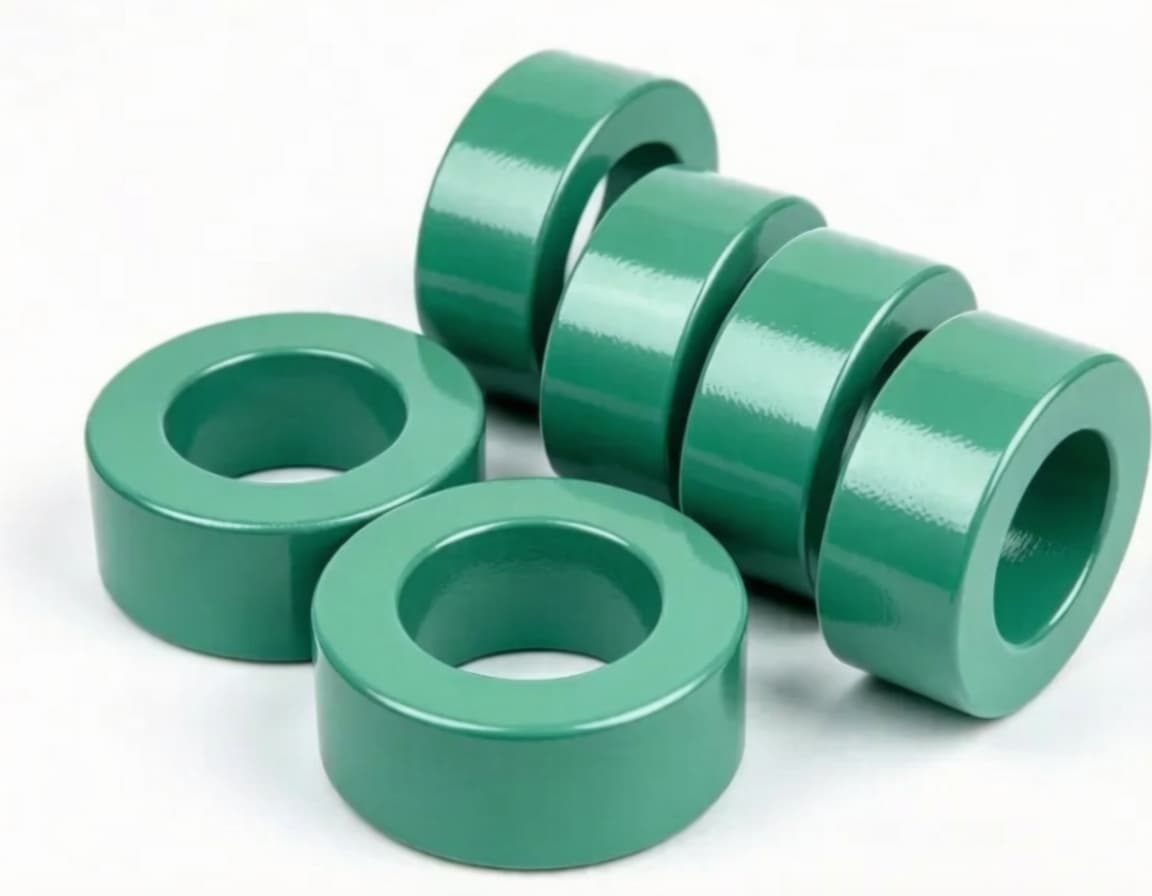
Industry requirements for magnetic cores used in AI server power supplies are now defined by concrete test conditions: inter-batch permeability deviation controlled within ±2.5%; sufficient margin reserved for Q-factor and loss at specified high-frequency points; loss increase not exceeding 15% under 100°C, designated frequency and flux density.
Note the nature of these specifications: they describe the distribution of a sample set, not just typical values. Only a handful of suppliers can satisfy all these criteria at once. A more direct benchmark: when inter-batch Bs dispersion of nanocrystalline cores is high, the efficiency variation of DC-DC modules can reach ±0.9%, while the target for some customers is ±0.3%.
A 0.6 percentage point gap often represents nearly all the efficiency gain achievable through topology optimization.
II. Fundamental Changes in Computing Power Power Supplies
Five key trends are amplifying parameter variance:
Surging power density. Power density has risen from 50 W/in³ to over 100 W/in³. A 5.5 kW unit fits into a 1U form factor; a GB200 NVL72 single rack delivers 120 kW, with each power shelf rated at 33 kW, consisting of six 5.5 kW PSUs in a 5+1 redundant parallel configuration. The 30% design margin that once absorbed fluctuations is no longer available.
Severe load transient conditions. Computing scheduling and variable workloads force the power supply to switch between light load, rated load and peak load within milliseconds. Traditional applications can rely on circuit margin for compensation, which is unworkable for computing loads. Saturation margin follows a statistical distribution instead of a fixed single value.
Extreme sensitivity to temperature rise. Compact rack layouts leave limited thermal headroom. Poor core consistency does not cause uniform overheating; instead, it triggers excessive hotspots on a single phase.
Parallel architecture as standard. Multi-phase Buck, multi-module current sharing and N+1 redundancy magnify inductance mismatch into ripple current and peak current discrepancies. Combined with inconsistent saturation margin, current-sharing margin is quickly depleted, and the continuously overloaded channel reaches its end-of-life first.
Magnetic integration and the 800V platform introduce coupling effects. TLVR topologies share coupled magnetic paths across multiple outputs, raising requirements from single-unit consistency to coupled consistency. On the 800V route, SST operates in the 20–50 kHz mid-frequency band. Analysis shows magnetic cores account for 33%–35% of the high-frequency transformer cost. Nanocrystalline material is the mature, mass-production-ready option, yet it demands far stricter batch-to-batch stability than ferrites.
In short: computing power power supplies are not simply higher-frequency or higher-power designs - they tolerate far less error.
III. What Consistency Truly Means
Consistency is far more than uniform dimensions. It refers to fully controllable, stable magnetic parameters: permeability dispersion, high-frequency loss, saturation flux density, temperature characteristics, plus stress effects introduced by fabrication, coating and winding. Amorphous and nanocrystalline materials are especially sensitive to process stress. Improper control in cutting, tape winding, curing or surface treatment will trigger performance drift.
It can be broken down into four layers:
Material layer: μi, Bs, Pcv, Curie temperature and DC-bias curves must remain stable together. Customers require a guaranteed performance envelope rather than nominal typical values.
Structural layer: AL value, air gap and tolerances. Gapped cores are highly sensitive; a 0.05 mm air gap deviation shifts AL significantly.
Process layer: Non-uniform furnace temperature during heat treatment leads to uncontrolled grain size, drifting both permeability and loss.
System layer: Mixing cores from three furnace runs, two production lines or two manufacturing sites may result in qualified individual batches but unacceptable overall distribution.
IV. Consequences of Minor Deviations
Imbalanced current sharing → hotspot temperature rise first
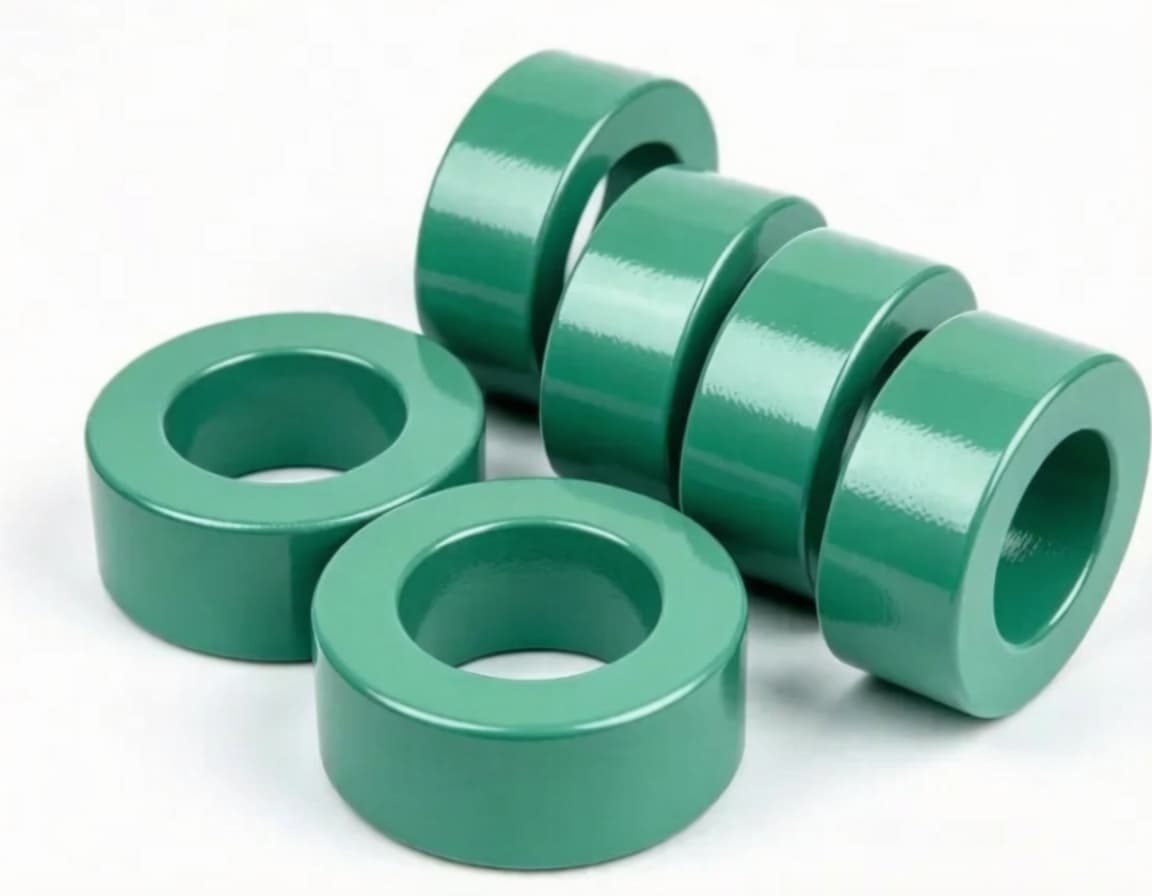
Permeability dispersion within a batch creates inductance mismatch across phases, unbalanced branch current and chronic overload on certain loops. With limited rack cooling margin, sustained hotspots either force derated operation or trigger over-temperature protection.
Loss dispersion erodes efficiency
If thermal design is based on average loss, cores with higher loss run persistently hot. If designed for worst-case loss, power density is sacrificed, contradicting miniaturization targets. For a 5.5 kW PSU, a 1-point efficiency drop generates an extra 55 W of heat at full load. For a 12-slot shelf, this adds up to 660 W of additional cooling load. A ±0.9% efficiency spread means a solution quoted at 97.5% may only achieve 96.6%, falling out of the Super Titanium efficiency tier.
Bias and saturation: the hardest fault to trace
In bidirectional, push-pull and full-bridge topologies, cores with inconsistent anti-bias capability are prone to local saturation. Inductance collapses, excitation current surges, and MOSFETs and capacitors endure extra stress. 7×24 operation rules out intermittent failures. Random saturation of this kind is a classic sporadic bug - it stems not from design flaws, but batch variation.
Temperature drift destabilizes control loops
Units may pass testing at ambient temperature, but parameter divergence occurs once temperature rises under full load. Inductance and loss shift accordingly, undermining dynamic response and loop stability. Loop instability causes oscillation and excessive ripple, interfering with downstream computing chips.
V. Shifting Priorities in Component Selection
Accordingly, more engineers prioritize the process control capability of magnetic material suppliers over sample performance metrics. Samples can be tuned for ultra-low loss, but the real competitive gap lies in locking the parameters of thousands of units within tight tolerance bands.
Five questions for secondary supplier qualification: Are the figures you provide typical values for this batch, or CpK data from the last 30 batches? Is variance dominated by within-batch scatter or batch-to-batch drift? What is the loss at 100°C under DC bias, and are these test conditions documented in the datasheet? What is the temperature uniformity of your heat treatment furnaces, and is furnace traceability available? How do you guarantee consistency across production line changes and manufacturing sites?
Suppliers who can answer these questions demonstrate capable process control; those who cannot rely on luck.
That said, tighter tolerances have limits. Overly strict specifications inflate cost and reduce yield, breaking the cost-performance balance. The rational approach is to define parameter ranges based on operating conditions, frequency and topology, and selectively tighten control on loss, permeability and stress stability - the parameters with the largest circuit impact. Tolerances can be relaxed for less critical properties.
Conclusion
Operating frequencies keep rising, power density continues to climb, and topologies keep evolving. Yet magnetic core parameter dispersion consumes all design margin built into upstream circuits.
Consistency is not about raising the upper limit of performance; it is about reducing variance.
A single outlier core, inside a 120 kW rack, can escalate into unplanned shutdowns, rejected acceptance tests or delayed deliveries. It makes little noise, yet it often decides success or failure.


